There are no items in your cart
Add More
Add More
| Item Details | Price | ||
|---|---|---|---|
Step-by-Step Walkthrough to Bring Your CAD Models into ROS Simulation
{{DATE}}
When building robots in ROS 2, one of the most common hurdles is turning your SolidWorks designs into URDF files that your robot can actually use for simulation, visualization, and control.
This guide, adapted from Krynsler Rebello’s comprehensive workflow, walks you through every step of converting SolidWorks assemblies to URDF (Unified Robot Description Format): from installation, coordinate setup, and export, to debugging and validation inside ROS tools like RViz and Gazebo.
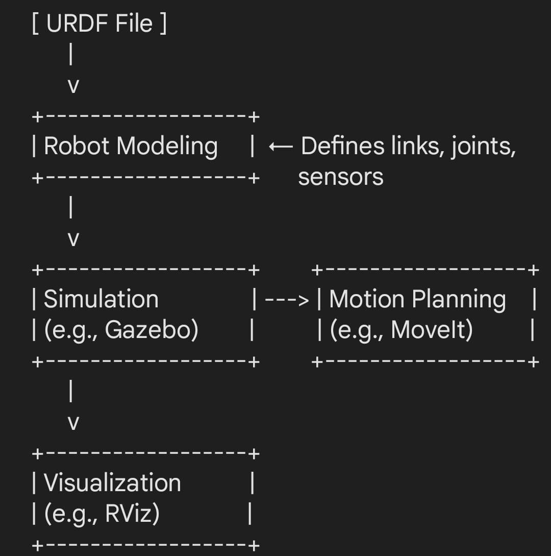
URDF acts as your robot’s digital twin inside ROS, describing every link, joint, and mesh file that makes up your robot. Done right, it bridges the gap between mechanical design and robotic intelligence.
URDF represents your robot as a tree of links and joints, defining physical parts, motion constraints, and inertial properties.
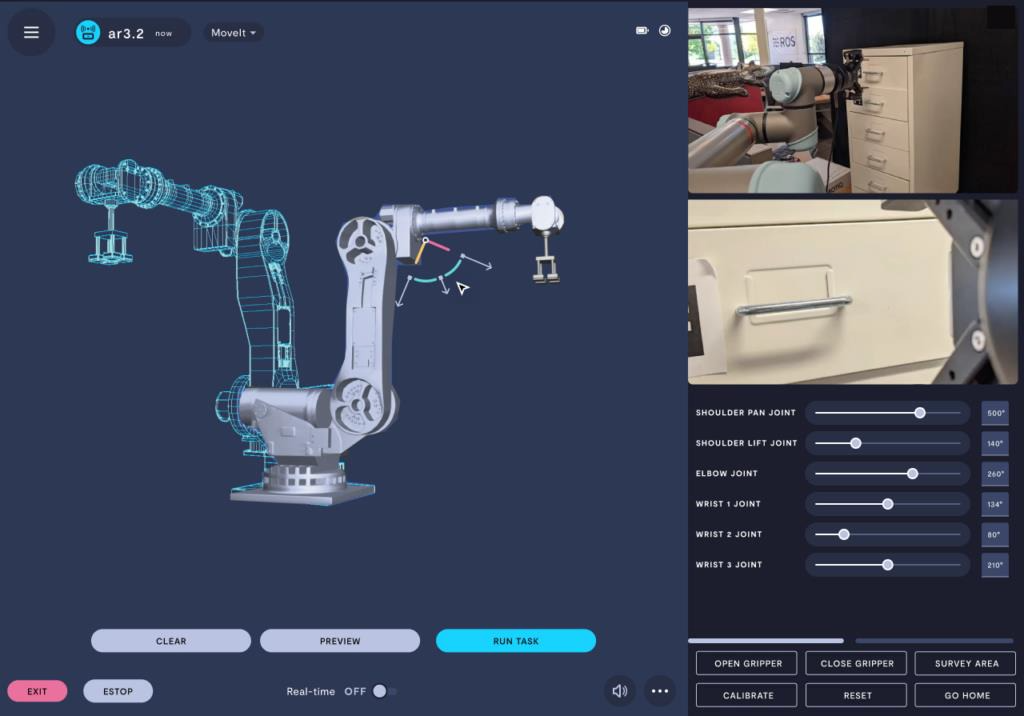
You’ll use it for:
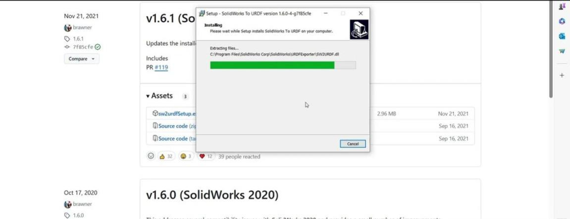
Before exporting, install the SW2URDF plugin from the ROS Wiki.
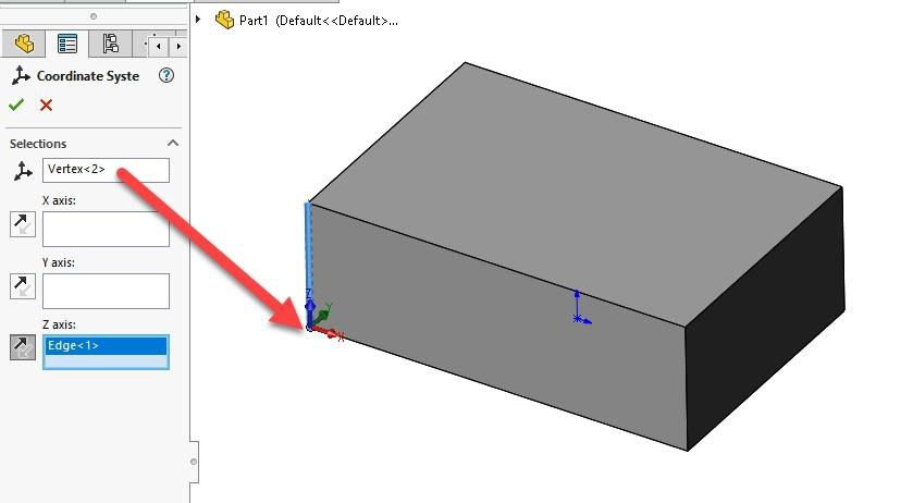
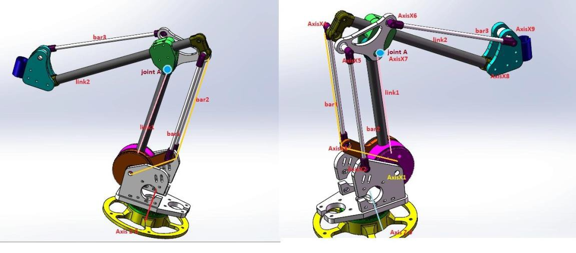
A successful export depends on how well your assembly is structured:
Open your SolidWorks assembly → Tools → Export to URDF.
urdf/robot.urdfmeshes/*.stllaunch/display.launch.py
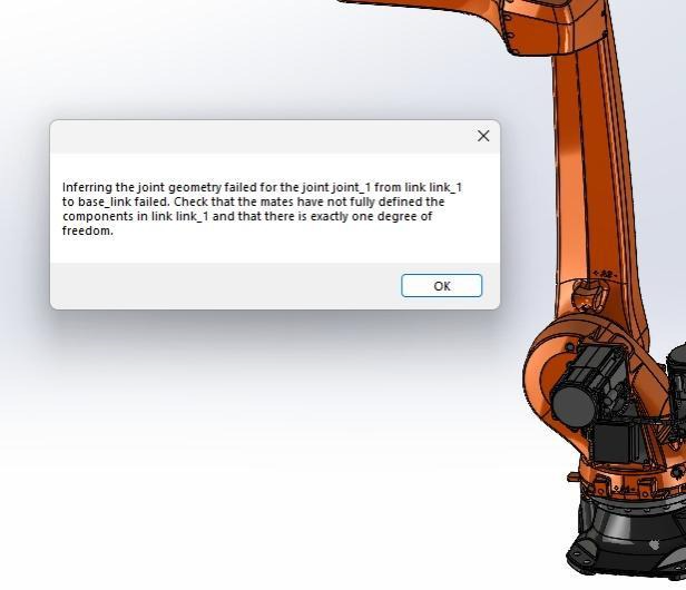
Encountered an error? You’re not alone.
Here’s how to solve frequent problems:
Your first export is just the beginning.
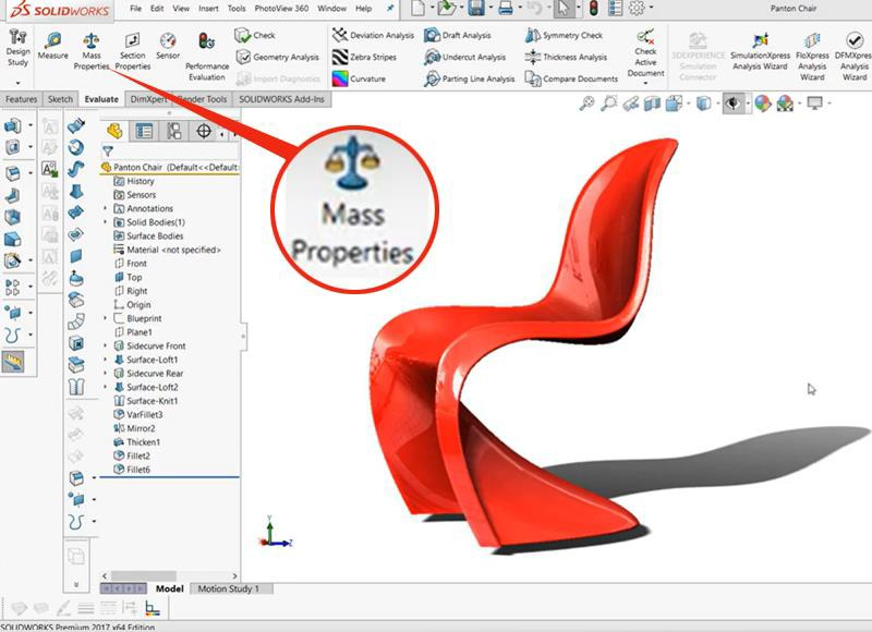
Before using your URDF:
XACRO adds variables, macros, and parameter reuse to URDF.
Define properties like wheel radius or joint limits once, then reuse them.
It’s cleaner, easier to modify, and essential for large robots.
Converting CAD to URDF isn’t just a mechanical export; it’s your robot’s first digital birth in the ROS world. With the right assembly structure, coordinate setup, and patience, you can go from CAD to simulation in a single afternoon.

{{AUTHOR}}
Author & Robotics Engineer | Contributor to Robocademy
 Launch your Graphy